
When I began my graduate studies, I was honestly not very knowledgeable about wireless communication systems. I had been involved, in some form or another, with amateur radio and designing my own antennas, but these hobbies only provided me with practical skills, and the knowledge I acquired then was hardly transferable to an academic setting. While in the stages of learning the correct technical terminology and standard practices in designing data-modulating systems, I quickly became aware at how most information in this field is either held in high-density papers with somewhat prohibitively formal language, or in dispersed online posts from over a decade ago. While there’s no shortage of YouTube tutorials on how to realistically simulate a single-path data stream, I found it hard to find full working coding examples of the systems I was learning about in my research and in class.
With this in mind, I began working on a common method for simulating wireless communication systems, saving the results and displaying graphics that communicate how these systems react under different scenarios. Now, nearly a year and half later, the project is finally in a state I feel proud to present to the public. This coding project was made with the hope of providing some illumination to incoming students, capable graduate students and technical hobbyists alike. It is written using MATLAB since the vast majority of my work was already spent using it, and I apologize to my Python researchers but MATLAB is just much easier for my geometry-inclined brain to understand. Regardless, it appears that many incoming students in my field are taught to use it as the software of choice, and all the required toolboxes should be prompted to install upon running for the first time, so perhaps it was a good decision to use MATLAB over Python if for no reason other than simplicity.
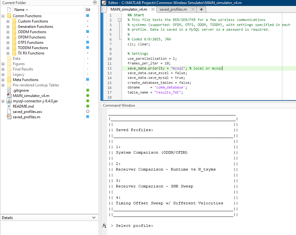
Figure 1: Control window for the main simulator file.
The simulator works in a similar way to how I had described in my post here, but with some added caveats. Figures are generated using profiles, which are saved in the “saved_profiles.m” file, naturally. Once the main simulator file is run, the user can select a profile to generate data on and the minimum number of frames per simulation point. Additional settings such as number of frames simulated per internal iteration, enabling/disabling parallelization, and local/MySQL saving settings can be configured at the top of the main file.
As of writing this, it is capable of simulating and comparing orthogonal frequency division multiplexing (OFDM), orthogonal time-frequency space (OTFS) and orthogonal delay-Doppler multiplexing (ODDM) systems, and I will likely be adding support for more modulation schemes in the future. All systems have the option to be simulated using realistic pulse shapes – specifically rectangular, sinc and root raised cosine (RRC) shaped pulses – and cyclic prefix can be toggled as desired. Cyclic prefix is not necessary in these systems, as they were designed with an inherent “wrap-around” effect in time-frequency space, but adding cyclic prefix is encouraged to compare with more traditional implementations. Below is a list of all the features currently implemented.
Table 1: Current feature support per system.
| System | Ideal Pulses | Realistic Pulses | Cyclic Prefix | CP-Less | Timing Offset | Supported Receivers |
|---|---|---|---|---|---|---|
| OFDM | ✔️ | ❌ | ✔️ | ✔️ | ✔️ | MMSE, DD-BDFE, CMC-MMSE |
| OTFS | ✔️ | ✔️ | ✔️ | ✔️ | ✔️ | ML, MMSE, BDFE |
| OTFS-DD | ✔️ | ✔️ | ✔️ | ✔️ | ✔️ | MMSE, MP, CMC-MMSE |
| ODDM | ✔️ | ✔️ | ✔️ | ✔️ | ✔️ | MMSE, MP, CMC-MMSE |
- OTFS is a more common implementation found in recent literature. OTFS-DD attempts to directly modulate data symbols to delay-Doppler space, and the method was developed by my advisor Dr. Jingxian Wu. OTFS supports non-truncated ideal, rectangular and sinc pulses, while OTFS-DD supports truncated rectangular, sinc and RRC pulses.
- OFDM without Cyclic Prefix is currently not supported. Please be patient.
If this project ends up being useful to you, please let me know via my contact page! I truly hope that this project can act as an educational tool for better understanding underlying design methodology and the physics that makes these systems work in the first place.
-JRW